Deltavox Deltavox

How to Choose a Hot Swappable Transceiver?

Time:2026-10-03 Author:Henry
0%

Choosing a hot swappable transceiver is not simply a matter of matching speed and connector type. The right module must fit the network’s real operating conditions. A careful choice protects uptime, signal quality, and future upgrade plans.

In practical deployments, engineers often begin with the switch model, port speed, and transmission distance. A 10GbE SFP+ module for a short server link differs greatly from a 100GbE QSFP28 module used across a data center row. Check the required fiber type, wavelength, reach, and duplex configuration. Then verify support for digital diagnostics monitoring, operating temperature, and power consumption. Small details matter. A module may physically fit while remaining unsupported by the platform.

Reliable selection also depends on evidence. Compare manufacturer datasheets, MSA specifications, IEEE requirements, and the switch vendor’s compatibility list. Review alarm thresholds and DOM readings before installation. These readings can reveal rising temperature, weak optical power, or unstable bias current. Test the transceiver with the intended switch and cable whenever possible. Bench testing is valuable.

No checklist is perfect. Firmware changes, coding restrictions, and undocumented vendor policies can still create problems. I have seen apparently compatible modules perform well in one switch but fail after a software update. That experience encourages a cautious process: confirm interoperability, purchase from a traceable supplier, and keep a tested spare nearby. A hot swappable transceiver should reduce service interruption, not introduce uncertainty. Good decisions balance technical specifications, operational experience, verified support, and the network’s actual environment.
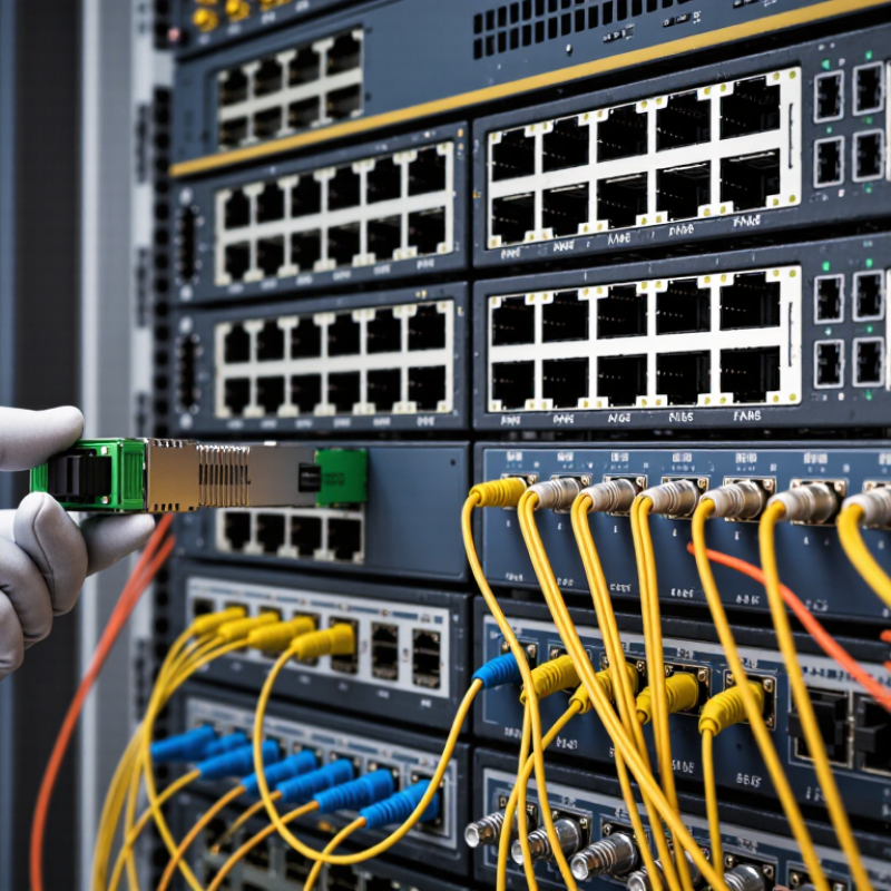
How to Choose a Hot Swappable Transceiver?

Understanding Hot-Swappable Transceivers and Their Applications

How to Choose a Hot-Swappable Transceiver?

Understanding hot-swappable transceivers begins with their role in live networks. They can be inserted or removed without shutting down compatible equipment. This matters in data centers, campus networks, storage systems, and telecom cabinets. The ITU Facts and Figures 2023 report estimated 5.4 billion people were online. That scale keeps network availability under pressure. A brief maintenance window can still disrupt critical services.

Match the transceiver to the switch port, speed, fiber type, and transmission distance. Check whether the port supports the required electrical standard and management functions. Digital diagnostics can show temperature, voltage, and optical power.

Useful details.
Also review the module’s power consumption and operating temperature. IEEE 802.3 specifications and SFF-8472 guidance provide important technical references. Do not rely on appearance alone. Identical housings may have different coding or compatibility limits.

Applications often determine the better choice. Short-range multimode modules suit connections inside one facility. Single-mode modules support longer links between buildings or network rooms. In dense racks, lower-power options can reduce heat and operating costs.

Yet “hot-swappable” does not mean risk-free. Dust, poor alignment, or incorrect firmware coding may cause link failure.

I have seen selection decisions focus on speed while ignoring reach and thermal conditions. That is an expensive oversight. Test one module in the actual port before wider deployment.

Identifying Compatibility Requirements for Network Equipment

How to Choose a Hot-Swappable Transceiver?

Identifying compatibility requirements starts with the network equipment, not the transceiver label. Check the port’s form factor, supported speed, and interface type. A small form-factor port may not accept a larger, high-density module. Confirm whether the connection uses single-mode fiber, multimode fiber, or copper. Distance also matters. A module designed for two kilometers may perform poorly across a longer campus link. I once focused on speed and overlooked wavelength matching. The installation worked briefly, then produced unstable optical readings.

Tips: Record the switch model, port type, firmware version, cable specification, and required distance. Compare these details with the equipment’s official compatibility documentation. Check power consumption and operating temperature, especially inside crowded racks. Digital monitoring can reveal temperature, voltage, and optical power before a failure becomes visible.

Hot-swappable operation does not remove compatibility risks. The equipment must support module replacement while powered, and the transceiver must match its electrical and management requirements. Some systems reject modules with unsupported identification data. Others accept them but disable monitoring functions. Verify coding, diagnostic support, link negotiation, and alarm behavior before deployment. Test one unit in a spare port first. That step feels slow, but it can prevent a wider outage. Compatibility charts are useful, though they are not perfect. Cable quality, dust, and bend radius can still change real-world performance. Keep the connector clean. A checklist helps, but careful observation remains necessary.

How to Choose a Hot Swappable Transceiver?

Identifying Compatibility Requirements for Network Equipment

Compare the typical maximum fiber reach of common Ethernet transceiver standards before selecting a hot-swappable module.

Compatibility checklist: Verify the equipment port form factor, supported Ethernet speed, optical standard, fiber type, wavelength, transmission distance, duplex mode, and host-system qualification requirements.

The reach values shown are typical maximum distances under the specified fiber conditions. Actual performance depends on fiber grade, connector quality, optical power budget, and network design.

Comparing Form Factors, Optical Types, and Transmission Specifications

How to Choose a Hot Swappable Transceiver?

Choosing a hot swappable transceiver starts with the equipment’s form factor. SFP modules suit one-gigabit and many ten-gigabit connections. SFP28 supports higher bandwidth in a similar footprint. QSFP designs serve dense forty, one-hundred, or higher-speed links. Check the switch port carefully. A module that fits physically may still fail electrically or through software compatibility. Review the port guide, supported coding, and power limits before installation.

Optical type should match both distance and fiber construction. Short-reach multimode optics work well inside a data hall, where links may span 100 meters. Single-mode optics support longer runs, sometimes reaching several kilometers. Bidirectional optics can use one fiber, but their paired wavelengths must match. Coarse or dense wavelength multiplexing can increase fiber capacity, although planning becomes less forgiving. Inspect connector cleanliness and bend radius. A small amount of dust can create unstable readings.

Transmission specifications deserve closer attention than the headline speed. Compare nominal data rate, wavelength, maximum reach, operating temperature, transmit power, receiver sensitivity, and power consumption. Digital monitoring can reveal temperature, voltage, and optical levels during operation. Fiber loss calculations should include patch panels and future repairs, not only the main cable. I once treated a “ten-kilometer” rating as a guarantee, which was careless. Real networks also face aging connectors, imperfect splices, and temperature changes. Leave engineering margin, and verify interoperability through testing rather than assuming every compliant module behaves identically.

How to Choose a Hot-Swappable Transceiver? Comparing Form Factors, Optical Types, and Transmission Specifications

Form Factor Typical Data Rate Electrical Lane Structure Common Optical Types Typical Transmission Distance Fiber and Connector Power and Thermal Profile Best-Fit Applications Key Selection Considerations
SFP 1 Gb/s 1 electrical lane Short-Reach multimode, Long-Reach single-mode, or copper direct-attach Up to approximately 550 m over multimode fiber; up to approximately 10 km over single-mode fiber, depending on the optical type Duplex LC for fiber; copper versions commonly use an RJ-45 interface Low power and compact thermal footprint Gigabit Ethernet access, aggregation, storage, and network uplinks Confirm the host port supports the required speed and that the transceiver is compatible with the network equipment and fiber plant
SFP+ 10 Gb/s 1 electrical lane SR, LR, ER, BiDi, or passive/active direct-attach cable Approximately 300 m over OM3 multimode fiber for SR; approximately 10 km for LR; longer reaches are possible with specialized optics Duplex LC is common for duplex fiber; simplex LC may be used for BiDi optics; cable versions use a fixed copper assembly Low to moderate power, generally suitable for dense 10 Gb/s systems 10 Gb/s server connections, enterprise aggregation, and data-center leaf-spine links Use matching wavelengths and fiber types at both ends; copper direct-attach cables are limited by cable length and equipment interoperability
SFP28 25 Gb/s 1 electrical lane SR, LR, ER, and passive/active direct-attach cable Approximately 70 m over OM3 or 100 m over OM4 for common SR implementations; approximately 10 km for LR Duplex LC for most duplex optical modules; fixed twinax assembly for direct-attach cables Low to moderate power with a compact footprint 25 Gb/s server access, high-density data-center networks, and storage connectivity A 25 Gb/s transceiver normally requires a host port designed for 25 Gb/s; automatic fallback to 10 Gb/s is equipment-dependent
QSFP+ 40 Gb/s 4 electrical lanes at approximately 10 Gb/s each SR4, LR4, and breakout-compatible direct-attach or active optical cable Approximately 100 m over OM3 or 150 m over OM4 for SR4; approximately 10 km for LR4 MPO/MTP-style multifiber connector for parallel optics; LC duplex for wavelength-multiplexed LR4 optics Moderate power and higher thermal density than SFP-family modules 40 Gb/s switch uplinks, server aggregation, and four-lane breakout connections Parallel optics require correct fiber polarity, lane order, and multifiber cabling; breakout operation must be supported by the host
QSFP28 100 Gb/s 4 electrical lanes at approximately 25 Gb/s each SR4, DR, FR, LR4, and direct-attach or active optical cable Approximately 70 m over OM3 or 100 m over OM4 for SR4; approximately 500 m for DR; approximately 2 km for FR; approximately 10 km for LR4 MPO/MTP-style connector for parallel-fiber optics; duplex or dual duplex LC for wavelength-multiplexed designs Moderate power; thermal requirements vary significantly by reach and optical complexity 100 Gb/s data-center spine and leaf links, server aggregation, and 4 × 25 Gb/s breakout Choose SR4 for short multimode links and DR/FR/LR for single-mode links; check whether the host supports 4 × 25 Gb/s breakout
QSFP56 200 Gb/s 4 electrical lanes at approximately 50 Gb/s each SR4, DR4, FR4, LR4, and direct-attach or active optical cable Common reaches include approximately 70–100 m for multimode SR4, 500 m for DR4, 2 km for FR4, and 10 km for LR4 MPO/MTP-style multifiber connector for parallel optics; LC-based connectors for some wavelength-multiplexed designs Moderate to high power and increased thermal requirements compared with QSFP28 200 Gb/s data-center interconnects, high-performance computing, and 4 × 50 Gb/s breakout Requires host equipment with 50 Gb/s-per-lane signaling; verify forward compatibility, modulation support, and breakout capability
QSFP-DD 400 Gb/s common; higher-rate variants are available 8 electrical lanes, commonly 8 × 50 Gb/s or 8 × 100 Gb/s depending on the implementation SR8, DR4, DR8, FR4, LR4, and direct-attach or active optical cable Approximately 100 m for common multimode SR implementations; approximately 500 m for DR; approximately 2 km for FR; approximately 10 km for LR, subject to the specific optical standard MPO/MTP-style multifiber connectors are common for parallel optics; duplex or dual duplex LC is used by some single-mode designs High power and significant thermal-management requirements; cage and airflow design are important 400 Gb/s spine, leaf, data-center interconnect, and high-density aggregation networks Confirm the exact lane rate, modulation, host gearbox support, cage specification, and module power class before installation
OSFP 400 Gb/s and 800 Gb/s classes Typically 8 electrical lanes; lane rate depends on the generation and implementation SR8, DR4, FR4, LR4, and parallel or wavelength-multiplexed single-mode designs Typical standardized reaches range from approximately 100 m for short-reach multimode optics to 2 km or 10 km for selected single-mode optics MPO/MTP-style connectors for parallel-fiber modules; LC-based connectors for some duplex single-mode modules High power and high thermal density; usually requires carefully designed airflow and a compatible cage High-capacity switching, large-scale data centers, artificial intelligence clusters, and high-performance computing OSFP and QSFP-DD are different mechanical ecosystems; verify the cage, faceplate, power budget, host signaling, and management interface
Selection rule: First match the form factor and host port, then select the required data rate, fiber type, optical reach, connector, lane configuration, power class, and operating temperature. Actual distance depends on fiber category, insertion loss, optical budget, splice quality, and the specific transceiver standard.

Evaluating Performance, Reliability, and Environmental Requirements

Choosing a hot-swappable transceiver starts with performance, reliability, and environmental fit. Match the module to the required data rate, wavelength, reach, and optical budget. Then verify receiver sensitivity and transmit power under real traffic. IEEE 802.3 specifications define interface limits, but laboratory results may differ from field behavior. Small errors matter. Digital optical monitoring can reveal rising temperature, bias current, and received power before failure appears. Reliability also depends on insertion cycles, latch strength, electrostatic protection, and firmware compatibility. Mean time between failures can mislead when connectors are repeatedly replaced. Uptime Institute’s Global Data Center Survey identifies power-related events as a leading cause of serious outages. A hot-swap design should reduce exposure during maintenance, not hide weak procedures.

Tips: Request independent test records for bit-error rate, thermal cycling, vibration, and insertion endurance. Compare readings at full load. Do not trust a single benchmark. Confirm whether alarms remain visible during removal and reinsertion.

Environmental requirements deserve equal attention. ASHRAE TC 9.9 recommends an equipment inlet range of 18–27°C for many data-center conditions, with controlled humidity and airflow. A transceiver rated for extended temperatures may still perform poorly beside a blocked fan. Check the declared operating range, altitude limits, condensation risk, dust protection, and cage airflow. IEC 62368-1 addresses equipment safety, while Telcordia requirements can support telecom reliability evaluations. Field engineers often find contamination near the optical port, not inside the module. I would not treat a wide temperature rating as complete protection. Test the module in the actual rack, with real airflow and maintenance habits.

Selecting a Supplier and Verifying Support Services

How to Choose a Hot Swappable Transceiver?

Selecting a supplier requires more than comparing unit prices. A reliable supplier should provide compatibility tables, firmware guidance, optical test records, and clear warranty terms. LightCounting’s 2024 market research valued the global optical transceiver market at more than 10 billion dollars, driven largely by data-center expansion. That growth also increases supplier differences. Ask whether each module is tested with your switch, cable distance, connector type, and operating temperature. Request sample units before purchasing in volume. Test removal and insertion while traffic remains active. Small details matter.

Support quality becomes visible during a fault. Uptime Institute’s 2024 Global Data Center Survey reported that more than half of respondents had experienced an outage within the previous three years. A supplier should offer defined response times, replacement procedures, remote diagnostics, and engineers who understand DOM readings, power levels, and link negotiation. Confirm spare-stock locations and return authorization steps. Check whether support continues after a firmware update. Do not accept vague promises. One practical concern is often overlooked: support documents may be technically correct but difficult to use during a midnight failure. I have seen teams choose low-cost modules, then lose hours proving a compatibility issue. A clear escalation path is worth more than a small discount. Even careful verification is imperfect, so record test results and review supplier performance after every deployment.

FAQS

What is a hot-swappable transceiver?

It is a network module that can be inserted or removed while compatible equipment remains powered. This reduces maintenance downtime. It still requires careful handling and supported hardware.

How do I check compatibility?

Match the module with the switch port, form factor, speed, fiber type, and distance. Check electrical standards, coding, firmware support, and power limits. A module may fit physically but fail electrically.

Which form factor should I choose?

Smaller modules suit common one-gigabit and ten-gigabit connections. Higher-density modules support forty-gigabit, one-hundred-gigabit, and faster links. Always follow the equipment guide.

Should I choose multimode or single-mode optics?

Multimode optics suit short links inside a facility, often around one hundred meters. Single-mode optics support longer connections between buildings or network rooms. Measure the real route, not just the cable length.

What specifications matter beyond speed?

Check wavelength, maximum reach, transmit power, receiver sensitivity, temperature range, and power consumption. Include patch panels, connectors, splices, and future repairs in the loss calculation. Headline speed is not enough.

Can one-fiber bidirectional modules simplify installation?

They can use one fiber and increase cabling flexibility. However, paired wavelengths must match at both ends. A mismatch can leave the link dark.

How can I monitor transceiver health?

Digital diagnostics can report temperature, voltage, bias current, and optical power. Review readings under full traffic, not only during idle periods. Watch for rising temperature or falling received power.

What environmental conditions should I consider?

Check inlet temperature, humidity, airflow, altitude, condensation risk, and dust exposure. A wide temperature rating cannot fix blocked ventilation. Inspect the rack beside the fan.

How should I test a new module?

Test one module in the actual port before wider deployment. Check traffic stability, optical levels, alarms, and reinsertion behavior. Do not trust one benchmark alone. I once focused too much on distance ratings. That was careless.

Conclusion

Choosing the right hot swappable transceiver requires more than matching a connector. First, understand how these modules support network upgrades, maintenance, and uninterrupted operation in data centers, enterprise networks, and telecommunications systems. Confirm compatibility with the equipment, including port type, electrical interface, firmware requirements, data rate, and supported transmission distance. A module that fits physically may still fail if its operating specifications or system requirements are different.

Next, compare available form factors, optical types, wavelengths, fiber modes, and transmission standards according to the intended application. Performance should be evaluated through bandwidth, latency, power consumption, operating temperature, and signal stability. Reliability is equally important, especially in systems that require continuous service or operate in demanding environments. Finally, select a supplier that can provide clear technical documentation, quality testing, warranty coverage, and responsive support. Verifying product certification, interoperability, replacement availability, and after-sales service can help reduce installation risks and ensure long-term network performance.

Henry

Henry

Henry is a dedicated marketing professional with a profound expertise in the company's offerings. With years of experience in the industry, he possesses an impressive understanding of the market dynamics and consumer behaviors that drive success. Henry is committed to sharing his insights through......